Sequential loads and segmental structural components are considered by assigning design load cases and structural elements to different load stages and they are applied by the load stage number sequentially, see Figure1. Applying a set of loads in the first load stage and keeping them constant in the second load stage with a set of additional loads allow us to simulate load sequence.
The strength, stability and deflection checks in the conventional design are essentially based on the complete structure without consideration of construction process. In fact, the behaviour of the components or units in the erection process may be different from the ideal case because instability and excessive deflection may occur in the construction stage with limited propping. Furthermore, shortening and undesirable deformations of the incomplete structure under self-weight and construction loads are inevitable. Generally speaking, the structural self-weight, external loads, boundary conditions and materials are depended on stages during the construction process and their variations are easily overlooked in conventional design.
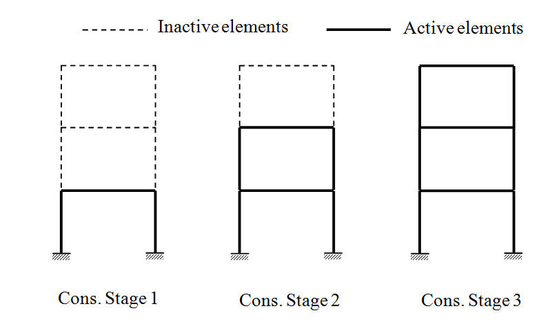
Figure1 Construction Sequence Analysis
The deformation and stress level during construction are key considerations by structural engineers.
Unlike previous work using the first-order linear analysis which treats the limit states design and the construction analysis as two separate procedures with analysis by computers and design by charts, the proposed method integrates analysis to design and therefore the design and analysis models are consistent. Moreover, the P-D and P-d effects, initial imperfections, pre-deformation and material yielding are all taken into account. The flow chart of the proposed procedure is shown in Figure2.
The steps in the flowchart in Figure2 are explained as follows.
(1) Define Construction Sequence
Engineers group structural elements in the design model into a number of construction units according to the construction scheme and assign each of them a unique “Construction ID”. Only the elements in the active groups are considered in analysis at a particular loading stage with other non-active structural elements ignored. New elements are added to the structure at initial stage.
(2) Apply Dead Loads (DL) and Construction Loads (CL)
Dead loads are mainly from the structural self-weight and a load factor of 1.2 is suggested. Construction loads include the live loads, self-weight of equipment and others.
(3) Pre-set Deformation
Excessive deflections can be reduced by pre-cambering through pre-set displacements.
(4) Construction Analysis
Stiffness matrix of the members in active groups is solved with the nonlinear incremental-iterative procedure adopted to improve convergence.
(5) Strength and Instability Check
With the consideration of initial imperfections and P-D and P-deffects, a fast and accurate instability and strength checks can be conducted by the section capacity check. Modification is needed when some members fail.
(6) Deflection Check
As checking for serviceability limit state, this step ensures deflection limit is not violated otherwise member re-sizing or pre-cambering is activated.
(7) Permanent Load Design Check
The conventional ultimate and serviceability limit state design load checks are carried out as the final safety and serviceability checks. The consideration of load sequence may affect the final force and moment distribution as some construction loads are present earlier than some members which do not share these construction loads.
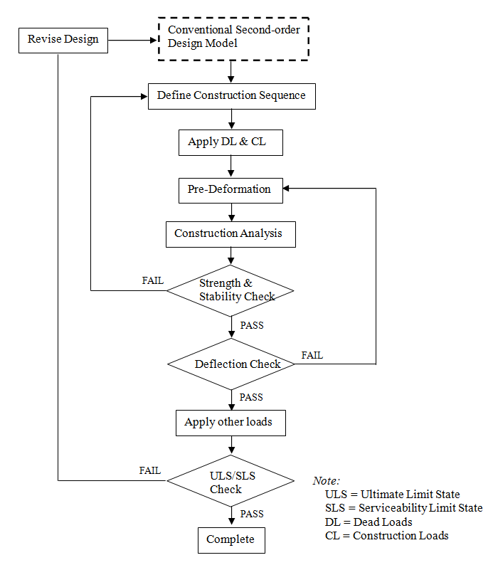
Figure2 Flow Chart of the Integrated Design and Construction Procedure