A semi-rigid connection must have the required strength, stiffness and ductility. Some typical moment versus rotation (M-θ) curves and various analytical and mathematical models representing the M-θ relationships can be found in previous chapters. Conveniently, a joint can be considered in an analysis as dimensionless with location at the intersection of the element centre lines. Further, a rotational spring element satisfying the M-θ relationship is inserted into each end of beam element to model the connection behaviour. The joint equilibrium condition can be expressed as,
![]()
(1)
in which Me and Mi are the moments at the two ends of a connection (see Figure1). The corresponding external node is connected to the global node and the internal node is joined to the beam element.
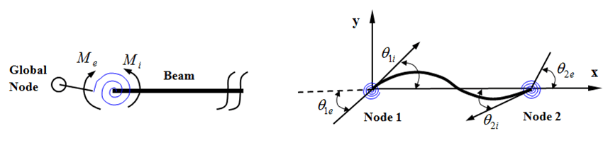
(a) Equilibrium at a joint (b) External and internal rotations
Figure1 Modeling of Semi-Rigid Jointed Member
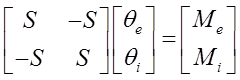
The stiffness of the connection, S, can be related to relative rotations at the two ends of the connection spring as,
![]()
(2)
where θe and θi are the conjugate rotations for the moments Meand Mi (see figure above). Rewriting Equation (2) in matrix form, the stiffness matrix of a connection spring can be written as,
(3)
A typical beam element bending stiffness matrix can be expressed as,
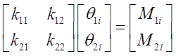
(4)
in which kij are the stiffness coefficients of a prismatic beam. Here, the imperfect PEP element proposed by Chan and Zhou (1995) is adopted and more details can be referred to the original reference. Therefore, a hybrid element can be obtained by directly adding the two ends connection stiffness to the PEP element bending stiffness matrix as,
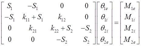
(5)
In which the first subscript refers to node 1 or node 2. The internal degrees of freedom of the stiffness expression can be eliminated by a standard static condensation procedure. The stiffness expression of a beam element with both ends connected to a pair of springs can be finally written as, ![]()
(6)
In which,
![]() ,
, ![]()
(7)
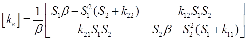
(8)
and β is given by,
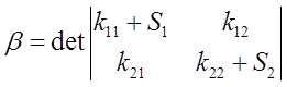
(9)
where S1 and S2 are the connection stiffness at nodes 1 and 2, respectively. When the spring stiffness Si is zero, it means that the corresponding end is pinned end; when the spring stiffness Si is infinite, it means that the corresponding end is rigid end. For semi-rigid case, the spring stiffness Si can be determined by the given M-θ function.