Questions:
For imperfection, the initial imperfection in the analysis is assumed as 0.00x of the member length with reference to BS5950 (where x is the input value and 1 is recommended in the manual.) Does such approach equivalent to the required frame imperfection (H/200) and member imperfection (L/200-500) in Structural Use of Steel 2005?
Reply:
The member imperfection (L/200-500) is input in section definition tab while the frame imperfection (H/200) is input in “General Settings -> Nonlinear Parameters ->Imperfection Direction -> Eigen value”. In default, the member imperfection is set as HK Steel Code 2005 or Eurocode-3 (2005) if you change the default. The frame imperfection (H/200) should be calculated and input by users or by program which finds the maximum linear dimension to determine the imperfection.
Question:
Do “Second-Order Analysis+Design” include “Beam Buckling Analysis” as well?
Reply:
“Second-Order Analysis + Design” will check section classification, beam buckling and so on. “Second-Order Analysis + Beam Buckling” and “Second-Order Analysis only” will not do section check such as use of elastic modulus for semi-compact sections but sometimes we need to do this for research studies on buckling of a structure unaffected by other factors.
Question:
For Plastic Advanced Analysis, there are two options, one is plastic hinge and one is plastic elements. I assumed it is refer as “plastic hinge model” and “plastic zone model” respectively in structural use of steel 2005. The manual has clear definition on it but the applicability, advantages or disadvantages has not been touch on. Can you give us some advice on these two methods?
Reply:
Both “Plastic hinge” and “Plastic element” are based on the plastic hinge approach. However, “Plastic element” is more conservative than “Plastic hinge”. The former keeps the resistance of the force and moment of the failed member constant when the section capacity factor is greater than 1.0 while the latter will keep the moment resistance of the failed member constant when the section capacity factor is greater than 1.
Question:
Under what circumstance shall we pick variable load increment for post-buckling analysis?
Reply:
For most cases, the "Constant Load Increment" (i.e. Newton-Raphson) method can give a quick good solution. If you want to trace the "Post-Buckling behavior", you can try "Variable Load Increment" method, i.e. "Arc-length + Minimum Residual Displacement". You can adjust the iterative and incremental parameters to control the load increment.
Question:
What is the difference between PEP element and Curved Stability Function? The default value for the program is PEP element, under what circumstance shall we pick Curved Stability Function?
Reply:
Both PEP element and Curved Stability Function are suitable for practical second-order analysis. However, they are two different approaches. In general, PEP is faster convergent and Curved Stability Function can be used for very large axial force case which is really too important for practical design.
Question:
Default Delta x L/1000 as indicated in the following picture? What value shall we input? I originally believed it is for imperfection. Thank you very much!
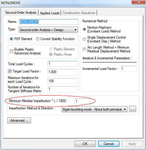
Reply:
It should be pointed out that the initial imperfections are so important for second-order analysis that we cannot ignore them. To avoid the user’s improper input, the minimum member imperfection defined by "delta x L/1000" will be automatically assigned to members when performing second-order analysis. This parameter is to ensure the structure as "imperfect".
Questions:
I wonder if you can assist with a problem to which I am sure the solution is staring me in the face, but which eludes me. I have attached two data files. The two structures are virtually identical except that the geometric properties of some of the members are a little different. Also, although the number of members is the same in both files, the number of nodes differs. I am looking for the lowest eigenvalue, but in spite of the fact that the two structures differ by so little, the eigenvalue for one is three times that for the other.
Reply:
The fault of your models is that the local axes of the vertical elements in the shorter lattice beams have their axes of bending in the wrong direction, so that the flexural stiffness of the lattice beams are much reduced by the subsequent flexibility.
Here shows the two convenience method to check the local axis:
- Open the 3D view of the whole model then check; or
- Click the “Show local axis button” button then to display the local axis to check.